
Damages to Ceramic Honeycomb in Reheating Furnaces
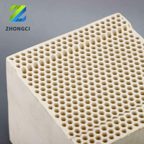
Most ceramic honeycomb regenerators in use today are made of mullite. Theoretically, their refractoriness and load softening point exceed 1400°C, fully meeting the requirement of flue gas temperatures below 1300°C in reheating furnaces. However, in practice, cracking or blockage often occurs. Based on operational data from multiple steel mill reheating furnaces, the main causes of damage are summarized as follows:
PART 01: Material Quality
Material selection is critical. Priority should be given to materials with excellent thermal shock resistance, high specific heat, and high density. Cracking mainly stems from improper material choice. Frequent temperature fluctuations caused by repeated flushing of flue gas and air impose strict demands on material performance. Many honeycombs in use have poor thermal shock resistance, making them prone to damage. The most common materials include mullite, alumina ceramic, dense cordierite, porous cordierite, and stoneware, with their chemical compositions and properties listed in Table 1.
PART 02: Operational Environment
Furnace scale and iron oxide in the material reduce the honeycomb’s refractoriness. The main components of honeycombs are Al₂O₃ and SiO₂. In reducing atmospheres, low-alumina materials form liquid phases below 1210°C even with minimal absorption of ferrous oxide, while high-alumina materials like mullite and corundum require higher temperatures (1380°C) and more ferrous oxide to form liquid phases.
PART 03: Design Flaws
Dual regenerators are widely used in regenerative reheating furnaces. Large nozzles for air and gas often lead to poor mixing and incomplete combustion. Residual air and gas entering the narrow honeycomb channels may cause secondary combustion, damaging the structure. Uneven flow of air (or gas) and flue gas in the regenerator can create local temperature deviations, generating thermal stress that shortens the honeycomb’s service life.
PART 04: Structural Design
Honeycomb pore spacing and wall thickness significantly affect temperature distribution during heat transfer, impacting service life. Too-small spacing can cause installation misalignment, reduce effective gas flow area, and increase pressure loss. Too-large spacing leads to poor heat exchange. Thus, an optimal structure must match specific operational conditions.